LOLSs is an acronym, which stands for LED O' LihSheng shield. It uses 3PWM on arduino to control brightness of RGB LEDs. If we use digital output instead of PWM, we could only turn on and off the LED, which is ..... BORING. Supply is 12V, can support about 6RGB LEDS (that is 3x8 LEDs in total)
Behold...


Now about RGB LED, in each of them there are 3 LEDs in total which is Red Green and Blue. Red is 2.2v, Blue and Green is 3.5v. Hence we need to use resistors such as 150ohm and 80ohm respectively to limit the current. If not, the LEDs will be burnt. Here, I tested my RGB LED with 1.5v, hence the dim green colour.


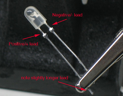
There are 4 "legs" from a normal LED, the longer leg is the anode which we connect the +ve side of VCC. The shorter legs are the cathode which we connect -ve or gnd.
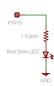
Now, how can we wire the LEDs to the arduino?
check out these diagrams by ADAFRUIT
Now, the fun part. Programming the RGB LED. We could do several of the below in code.
1. Light the colour one by one
2. Fade the brightness of the RGB LEDs with PWM. There is example code to fade 1 LED. It is available at Examples->Basics->Fade
3. Mix colour of the RGB LED. the value of RGB LED follow this format [255,255,255]. For each colour, 0 to turn off, 255 to turn on. Any values in between is to change the brightness. If all 3 led is 255, what is the resulting colour=? WHITE
3. Make the colour change according to music
4.etc etc
Here is my rendition of RGB led with Arduino, based on the sample code given.
code here

No comments:
Post a Comment